SIMPLE VAPOUR COMPRESSION SYSTEM
Out of all refrigeration systems, the vapour compression system is the most important system from the view point of commercial and domestic utility. It is the most practical form of refrigeration. In this system the working fluid is a vapour. It readily evaporates and condenses or changes alternately between the vapour and liquid phases without leaving the refrigerating plant.
During evaporation, it absorbs heat from the cold body. This heat is used as its latent heat for converting it from the liquid to vapour. In condensing or cooling or liquefying, it rejects heat to external body, thus creating a cooling effect in the working fluid. This refrigeration system thus acts as a latent heat pump since it pumps its latent heat from the cold body or brine and rejects it or delivers it to the external hot body or cooling medium.
The principle upon which the vapour compression system works apply to all the vapours for which tables of Thermodynamic properties are available.
Simple Vapour Compression Cycle
In a simple vapour compression system fundamental processes are completed in one cycle These are:
- Compression
- Condensation
- Expansion
- Vaporization
The flow diagram of such a cycle is shown in Fig. 1
The vapour at low temperature and pressure (state ‗2‘) enters the ―compressor‖ where it is compressed isentropically and subsequently its temperature and pressure increase considerably (state ‗3‘). This vapour after leaving the compressor enters the condenser where it is condensed into high pressure liquid (state ‗4‘) and is collected in a ―receiver tank‖. From receiver tank it passes through the ―expansion valve‖, here it is throttled down to alower pressure and has a low temperature (state ‗1‘). After finding its way through expansion―valve‖ it finally passes on to ―evaporator‖ where it extracts heat from the surroundings or circulating fluid being refrigerated and vapourises to low pressure vapour (state ‗2‘).
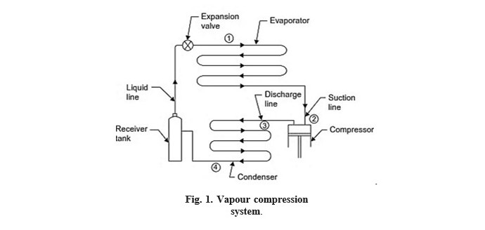
Fig. 1. Vapour compression system.
Merits and demerits of vapour compression system over Air refrigeration system: Merits:
- O.P. is quite high as the working of the cycle is very near to that of reversed Carnot cycle.
- When used on ground level the running cost of vapour-compression refrigeration system is only 1/5th of air refrigeration
- For the same refrigerating effect the size of the evaporator is
- The required temperature of the evaporator can be achieved simply by adjusting thethrottle valve of the same
Demerits:
- Initial cost is
- The major disadvantages are inflammability, leakage of vapours and These havebeen overcome to a great extent by improvement in design.
Functions of Parts of a Simple Vapour Compression System
Here follows the brief description of various parts of a simple vapour compression system shown in Fig. 1.
- The function of a compressor is to remove the vapour from the evaporator, and to raise its temperature and pressure to a point such that it (vapour) can be condensed with available condensing media.
- Discharge line (or hot gas line). A hot gas or discharge line delivers the high-pressure, high-temperature vapour from the discharge of the compressor to the
- The function of a condenser is to provide a heat transfer surface through which heat passes from the hot refrigerant vapour to the condensing medium.
- Receiver A receiver tank is used to provide storage for a condensed liquid so that a constant supply of liquid is available to the evaporator as required.
- Liquid A liquid line carries the liquid refrigerant from the receiver tank to the refrigerant flow control.
- Expansion valve (refrigerant flow control). Its function is to meter the proper amount of refrigerant to the evaporator and to reduce the pressure of liquid entering the evaporator so that liquid will vapourize in the evaporator at the desired low temperature and take out sufficient amount of
- An evaporator provides a heat transfer surface through which heat can pass from the refrigerated space into the vapourizing refrigerant.
- Suction The suction line conveys the low pressure vapour from the evaporator to the suction inlet of the compressor.
Vapour Compression Cycle on Temperature-Entropy (T-s) Diagram
We shall consider the following three cases:
- When the vapour is dry and saturated at the end of Fig. 2 represents the vapour compression cycle, on T-s diagram the points 1, 2, 3 and 4 correspond to the state points 1, 2, 3 and 4 in Fig. 1.
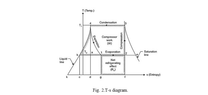
Fig. 2.T-s diagram.
At point ‗2‘ the vapour which is at low temperature (T2) and low pressure enters the compressor‘scylinder and is compressed adiabatically to ‗3‘ when its temperature increases to thetemperature T. It is then condensed in the condenser (line 3-4) where it gives up its latent heat tothe condensing medium. It then undergoes throttling expansion while passing through the expansionvalve and it‘s again reduces to T1, it is represented by the line 4-1. From the T-s diagram itmay be noted that due to this expansion the liquid partially evaporates, as its dryness fraction is represented by the ratio (b1/b2). At ‗1‘ it enters the evaporator where it is further evaporated atconstant pressure and constant temperature to the point ‗2‘ and the cycle is completed.
Work done by the compressor = W = Area ‗2-3-4-b-2 Heat absorbed = Area 2-1-g-f-2‘

(h1= h4, since during the throttling expansion 4-1 the total heat content remains unchanged)
- When the vapour is superheated after If the compression of the vapour is continued after it has become dry, the vapour will be superheated, and its effect on T-s diagram is shown in Fig. 3. The vapour enters the compressor at condition ‗2‘ and is compressed to ‗3‘ where it is superheated to temperature T sup .Then it enters the condenser. Here firstly superheated vapour cools to temperature T1(represented by line 3-3‘ ) and then it condenses at constant temperature along the line 3‘ -4 ; the remaining of the cycle ; however is the same as before.
Now, Work done = Area 2-3-3‘ -4-b-2
and Heat extracted/absorbed = Area 2-1-g-f-2
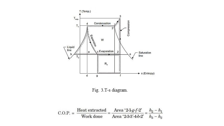
Fig. 3.T-s diagram.
In this case h3= h3+ cp(Tsup.– Tsat.) and h3= total heat of dry and saturated vapour at thepoint ‗3 ‘.
- When the vapour is wet after Refer Fig. 4 Work done by the compressor = Area 2-3-4-b-2
Heat extracted = Area 2-1-g-f-2
![]()
Note. If the vapour is not superheated after compression, the operation is called ‗WET
COMPRESSION‘ and if the vapour is superheated at the end of compression, it is known as
‗DRY COMPRESSION‘. Dry compression, in actual practice is always preferred as it gives higher volumetric efficiency and mechanical efficiency and there are less chances of compressor damage.
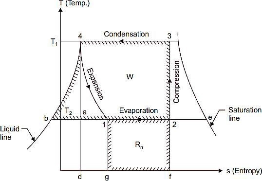
Fig. 4 T-s diagram.
Simple Vapour Compression Cycle on p-h Chart
Fig. 5 shows a simple vapour compression cycle on a p-h chart. The points 1, 2, 3 and 4 correspond to the points marked in Fig. 1
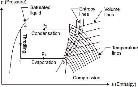
Fig. 5.Simple vapour compression cycle on p-h chart.
The dry saturated vapour (at state 2) is drawn by the compressor from evaporator at lower pressure p1 and then it (vapour) is compressed isentropically to the upper pressure p2. The isentropic compression is shown by the line 2-3. Since the vapour is dry and saturated at the start of compression it becomes superheated at the end of compression as given by point
- The process of condensation which takes place at constant pressure is given by the line 3-4. The vapour now reduced to saturated liquid is throttled through the expansion valve and the process is shown by the line 4-1. At the point 1 a mixture of vapour and liquid enters the evaporator where it gets dry saturated as shown by the point 2. The cycle is thus completed. Heat extracted (or refrigerating effect produced),
Rn=h2-h1 W=h3-h1
![]()
The values of h1, h2 and h3 can be directly read from p-h chart.
Factors Affecting the Performance of a Vapour Compression System
The factors which affect the performance of a vapour compression system are given below :
- Effect of suction The effect of decrease in suction pressure is shown inFig. 6. The C.O.P. of the original cycle,
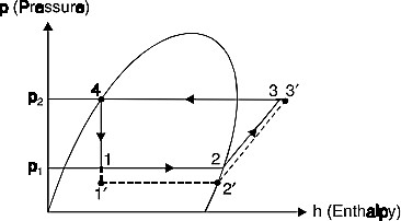
Fig. 6.Effect of decrease in suction pressure.
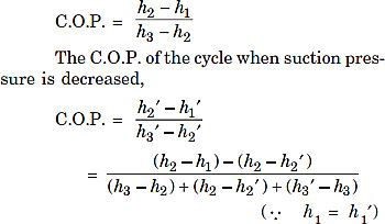
This shows that the refrigerating effect is decreased and work required is increased. Then net effect is to reduce the refrigerating capacity of the system (with the same amount of refrigerant flow) and the C.O.P.
- Effect of delivery Fig. 7 shows the effect of increase in delivery pressure.
C.O.P. of the original cycle,
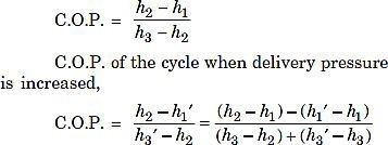
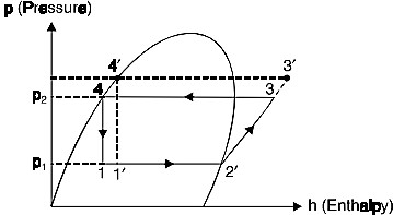
Fig. 7 Effect of increase in delivery pressure
The effect of increasing the delivery/discharge pressure is just similar to the effect of decreasing the suction pressure. The only difference is that the effect of decreasing the suction pressure is more predominant than the effect of increasing the discharge pressure.
The following points may be noted:
- As the discharge temperature required in the summer is more as compared with winter, the same machine will give less refrigerating effect (load capacity decreased) at a higher
- The increase in discharge pressure is necessary for high condensing temperatures and decrease in suction pressure is necessary to maintain low temperature in the Effect of superheating. As may be seen from the Fig. 8 the effect of superheating is to increase the refrigerating effect but this increase in refrigerating effect is at the cost of increase in amount of work spent to attain the upper pressure limit. Since the increase in work is more as compared to increase in refrigerating effect, therefore overall effect of superheating is to give a low value of C.O.P.

Fig. 8.Effect of superheating.Fig. 9.Effect of sub-cooling of liquid.
- Effect of sub-cooling of ‗Sub-cooling‘ is the process of cooling the liquid refrigerant below the condensing temperature for a given pressure . In Fig. 14.18 the process of subcooling is shown by 4-4 . As is evident from the figure the effect of subcooling is to increase the refrigerating effect. Thus sub-cooling results in increase of C.O.P. provided that no further energy has to be spent to obtain the extra cold coolant required.
The sub-cooling or under cooling may be done by any of the following methods: (I ) Inserting a special coil between the condenser and the expansion valve. (ii) Circulating greater quantity of cooling water through the condenser.
- Using water cooler than main circulating
- Effect of suction temperature and condenser The performance of the vapour compression refrigerating cycle varies considerably with both vapourising and condensing temperatures. Of the two, the vapourising temperature has far the greater effect. It is seen that the capacity and performance of the refrigerating system improve as the vapourising temperature increases and the condensing temperature decreases. Thus refrigerating system should always be designed to operate at the highest possible vapourising temperature and lowest possible condensing temperature, of course, keeping in view the requirements of the application.
- An ammonia refrigerator process 20tons of ice per day from and at 0°C.The condensation and evaporation takes at 20°C and -20°C respectively the temperature of the vapour at the end of Isentropic compression is 50°C and there is no under cooling of the COP=70% of theoretical COP. Determine (i) Rate of NH3circulation (ii) size of compressor, N=240rpm,L=D, ηvol=80%. Take Laten heat of Icc=335kJ/kg, Cp= 2.8 kJ/kg,
Vs1=0.624m3kg. Use the following properties of ammonia.
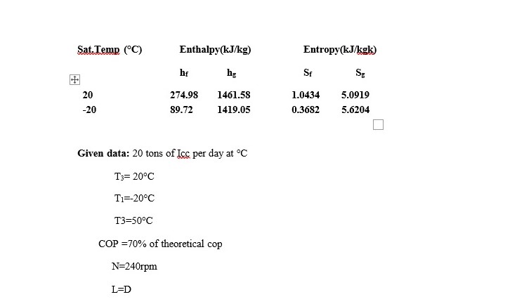
hv=80%
Latent heat of Ice=335KJ/kg Cp=2.8KJ/kgk
Vs1=0.624m3/kg
Solution:-
The refrigeration effect=20×3.5=77.55kw h1=1419.05KJ/kg hg2=1461.58KJ/kg
at 20°C hf3=274.98 KJ/kg
h2=hg2+Cp (T2-20) h2=1461.58+2.8(50-20) h2=1545.58 KJ/kg COP= (h1-hf3)/(h1-h2)
= (1419.05-274.98)/(1545.58-1419.05) =9.04.
- A 5 tonne refrigerator plant uses RR as It enters the compressor at -5°C as saturated vapour. Condensation takes place at 32°C and there is no under cooling of refrigerant liquid. Assuming isentropic compression, determine COP of the plant, mass flow of refrigerant, power required to run the compressor in kw. The properties of R-12 are given table.

Solution:
Beginning of compression in dry and end of compression is superheated. So the P-h and T-S diagrams are
From table, at point 1 T1=-5°C=268K
hg1=2493kJ/kg , Sg1=1.557KJ/kgk At point 2
T2=32°C=305k, hf2=130.5KJ/kg, hg2=264.5, Sg2=1.542KJ/kgK
From ph diagram, At point eqn(1) (dry).
At -5°C, i.e at 268k hg1=249.3KJ/kg=hg h1=249.3KJ/kg
At 32°C, i.e at 305K hg2=264.5KJ/kg=h2′
h2’=264.5KJ/kg
Entropy is constant during the compression process so, S1=S2
From T- S diagram
At point (1) dry,
S1=Sg at -5°C
S1=Sg1=1.557KJ/kgk S1=S2=1.557KJ/kgk
At point (2) (super heated) S1=S2′ + Cpln (T2/T2′)
1.557=S2’+1.884 ln(T2/305)——– (1) S2’=Sg at 32°C.
Sg2=1.542=S2 S2’=1.542KJ/kg k 1.884 ln (T2/305)=0.015
T2=307.44k
For super heated vapour the enthalpy is
h2=h2’+Cp(T2-T1′)
h2= 264.5 + 1.884 (307.44-305)
h2= 269.1 KJ/kg
From P-h diagram, we know that, h3= h4
h3=hf at 32°C
hf 2=130.5= hf We Know that,
COP=Refrigeration effect / Work done= (h1-h4)/ (h2-h1)
= (2493-130.5)/(269.1-249.3)=6
Refrigeration effect = m× (h1- h4)
m= (2×210)/ (249.3-130.5)
m = 8.84Kg/min Work done = Refrigeration effect/ cop
= (2×210)/6 = 175 KJ/min
Power = 2.92kw.
- A refrigerator works between -7°C and 27°C the vapour is dry at the end of adiabatic Assuming there is no under cooling determine (i) cop (ii) power of the compressor to remove a heat load of 12140KJ/hr.The properties of refrigerant are given
| T(°C) | sensible Heat (hf) | Latent heat(hfg) KJ/kgk) | Entropy of liquid
(KJ/kgk) |
Entropy of vapourSg (KJ/kgk) |
| -7 | -29.3 | 1297.9 | -0.109 | 4.748 |
| 27 | 1117.23 | 1172.3 | 0.427 | 4.333 |
in table.
Solution:
The vapour is dry at end of compression i.e, beginning of compression is wet and of compression is dry saturated.
At point (1)
T1=-7°C=266k, hfg1=1297.9 KJ/kg, Sf1=-0.109 KJ/kgK
hf1=-29.3 KJ/kg, Sfg1=4.478 KJ/kgK
At point (2)
T2=27°C=300k, hfg2=1172.3 KJ/kg, Sf2= 0.427KJ/kgK
hf2=117.23 KJ/kg, Sfg2=4.333KJ/kgK We point S1=S2
At point (1) (wet) S1=Swet=Sf1+x1+Sfg 1S1= -0.109+x1(Sfg1-
Sf1) (Sfg=Sg-Sf)
S1= -0.109+x1(4.857)
At point (2) (dry) S2=Sg2=4.33KJ/kgK S2=4.33KJ/kgK
S1=S2 So,4.33= -0.109+x1(4.857)
Dryness fraction
x1=0.913
At point (1) (wet) h1= hf1+ x1× hfg1
h1=-29.3+0.913×1297.3 h1=1156.3 KJ/kg
At point (2) (dry) h2= hf2+hg2
h2= 117.23+1172.3
h2= 1289.53 KJ/kg
From P-h diagram h3=h4
h3=hf2
h3=1172.3 KJ/kg h4=117.23
KJ/kgCOP= (h1- h4)/ (h2-h1) =
(1156.3-117.23) /
(1289.53-1156.3)
= 7.7Work done
= Heat removed/
COP
= 12140/7.7
Power = 0.43 KJ/hr
See also:
Psychrometry and Air conditioning
