The compressor is the main moving component of the vapour-compression system. It provides the system with the force to draw the vapour from the evaporator, to force it into the condenser by creating a high pressure and to maintain circulation of the refrigerant.
The compressor’s work begins by its creating a low-pressure region on the low side of the system, which allows the low-temperature vapour to flow from the evaporator through the suction line to the compressor. The compressor then compresses the low-temperature vapour, raising its vapour pressure and temperature. This high- temperature and high-pressure vapour, containing the heat absorbed from the evaporator and during compression, is discharged to the condenser. The heat then flows from the hot vapour into the cooler air or water around the condenser.
1. Reciprocating compressor
The compressor in which vapour refrigerant is compressed by reciprocating motion of the piston are called reciprocating compressor.
- Piston and cylinder arrangement to provide compressive force – like IC
- Reciprocating motion of the piston due to external power compresses the refrigerant inside the
- These compressors used for refrigerants which have low volume per kg such as ammonia, R-717, R-12, R-22, R-40.
- In single acting reciprocating compressor, the suction, compression and discharge of refrigerant takes place in one revolution of crank In double acting reciprocating compressor, the suction, compression takes place on both side of piston
Working principle of single stage single acting reciprocating compressor
The reciprocating compressor basically consists of a cylinder with a piston fitting closely inside. When the piston moves downwards, a low pressure is produced above it in the cylinder as the refrigerant left in the clearance space expands. When the pressure becomes less than the suction line pressure, the pressure in the suction line forces the suction valve open and vapour enters the cylinder. The flow continues till the piston touches the bottom dead centre. The suction valve closes due to spring action at this point. When the piston moves upwards, the vapour is compressed and, when its pressure is greater than the pressure in the discharge line, the discharge valve is forced open and the high pressure high temperature refrigerant is discharged.
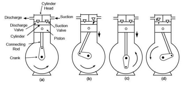
Different parts of the Reciprocating compressor
Piston : The piston is generally made of cast-iron. Piston it fitted with close tolerance in cylinder. The function of the piston is only to compress the refrigerant in an enclosed cylinder.
Crank shaft: Crank shaft is a moving lever. When it is used with the connecting rod it moves with the reciprocating motion.
Connecting rod: Connecting rod is used for connecting the piston and crank shaft. One end is connected to the piston by means of hardened, ground and highly polished steel wrist pin. The wrist pin upper end of the connecting rod have an oscillating or reciprocating motion while the lower end of the connecting rod combines a reciprocating and rotary motion.
Suction and discharge valve: The valve that controls the flow of refrigerant from the suction line into cylinder head is known as suction valve. The valve that discharges the compressed gas towards the discharged line is called discharged valve.
2. Rotary compressor
In rotary compressors, the vapour refrigerant from the evaporator is compressed due to the movement of blades. The clearance in this type of compressor is negligible, thus, possesses high volumetric efficiency. Common type refrigerants used are R-12, R-22, R-114 and ammonia.
Two types
(A) Single stationary blade type rotary compressor
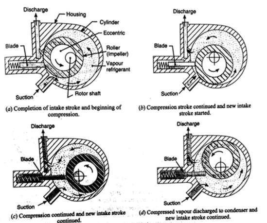
This consists of a stationary cylinder, a roller (or impeller) and a shaft. The shaft has an eccentric on which the roller is mounted. A blade is set into the slot of a cylinder in such a manner that it always maintains contacts with the roller by means of a spring. The blade moves in and out of the slot to follow the rotor when it rotates. When the shaft rotates, the roller also rotates so that it always touches the cylinder wall.
Figure (a) shows the completion of intake stroke (i.e. the cylinder is full of low pressure and temperature vapour refrigerant) and the beginning of compression stroke. When the roller rotates, the vapour refrigerant ahead of the roller is being compressed and the new intake from the evaporator is drawn into the cylinder, as shown in figure (b). As the roller turns mid position as shown in figure (c), more vapour refrigerant is drawn into the cylinder while the compressed refrigerant is discharged to the condenser. At the end of compression stroke as shown in figure (d), most of the compressed vapour refrigerant is passed through the discharge port to the condenser. A new charge of refrigerant is drawn into the cylinder. This, in turn is compressed and discharged to the condenser. In this way, the low pressure and temperature refrigerant is compressed gradually to a high pressure and temperature.
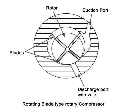
(B) Rotating blade type rotary compressor
This compressor consists of a cylinder and a slotted rotor containing a number of blades. The centre of the rotor is eccentric with the centre of the cylinder. The blades are forced against the cylinder wall by the centrifugal action during the rotation of the motor. The low pressure and low temperature vapour refrigerant from the evaporator is drawn through the suction port. When the rotor turns, the vapour refrigerant entrapped between the two adjacent blades is compressed and discharged through the discharge port to the condenser.
-
Centrifugal compressor
This compressor increases the pressure of low pressure vapour refrigerant to a high pressure vapour refrigerant by means of centrifugal force. The centrifugal compressor is generally used for refrigerant that require large displacement and low condensing pressure, such as R-11 and R-113.
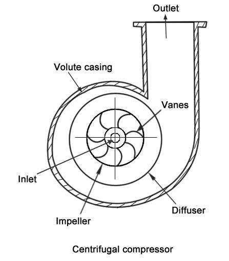
A single stage centrifugal compressor, in its simplest form, consists of an impeller to which a number of curved vanes are fitted symmetrically, as shown in Fig. The impeller rotates in an air tight volute casing with inlet and outlet points. The impeller draws in low pressure vapour refrigerant from the evaporator. When the impeller rotates, it pushes the vapour refrigerant from the centre of the impeller to its periphery by centrifugal force. The high speed of the impeller leaves vapour refrigerant at a high velocity at the vane tips of the impeller. The kinetic energy thus attained at the impeller outlet is converted into pressure energy when the high velocity vapour refrigerant passes over the diffuser. The volute casing collects the refrigerant from the diffuser and it further converts the kinetic energy into pressure energy before it leaves the refrigerant to the condenser.
Advantages and disadvantages of Centrifugal Compressors over reciprocating compressor Advantages
- Since the centrifugal compressors have no valves, pistons, cylinders, connecting rod, , therefore the working life of these compressors is more as compared to Reciprocating compressors.
- The operation of centrifugal compressors is quiet and
- The centrifugal compressors run at high speeds (3000 p.m. and above), therefore these can be directly connected to electric motors or steam turbines.
- Handle larger volume of vapour refrigerant as compared to reciprocating compressor
- The centrifugal compressors are especially adapted for systems ranging from 50 to 5000 They are also used for temperature ranges between – 90°C and + 10°C.
- The efficiency of these compressors is considerably
- Requires less floor area
Disadvantages
- When refrigeration load decreases below 35 percent of the rated capacity, surging Surging is the reverse flow of refrigerant from compressor to evaporator when refrigeration load decreases.
- The increase in pressure per stage is less as compared to reciprocating
- The centrifugal compressors are practical below 50 tonnes capacity
4. Hermetic compressor
When compressor and motor operates on same shaft and enclosed in a common casing, these are known as hermetic compressor. These compressors may operate on reciprocating or rotary principle. These are widely used in domestic refrigerators, home freezers and window AC.
