Cooling towers overcome most of these problems and therefore are commonly used to dissipate heat from water-cooled refrigeration, air-conditioning, and industrial process systems. The water consumption rate of a cooling tower system is only about 5% of that
of a once-through system, making it the least expensive system to operate with purchased water supplies. Additionally, the amount of heated water discharged (blowdown) is very small, so the ecological effect is greatly reduced. Lastly, cooling towers can cool water to within 4 to 5°F of the ambient wet-bulb temperature, or about 35°F lower than can air-cooled systems of reasonable size. This lower temperature improves the efficiency of the overall system, thereby reducing energy use significantly and increasing process output.
Water to be cooled is distributed in the tower by spray nozzles, splash bars, or film-type fill, which exposes a very large water surface area to atmospheric air.
Atmospheric air is circulated by (1) fans, (2) convective currents, (3) natural wind currents, or (4) induction
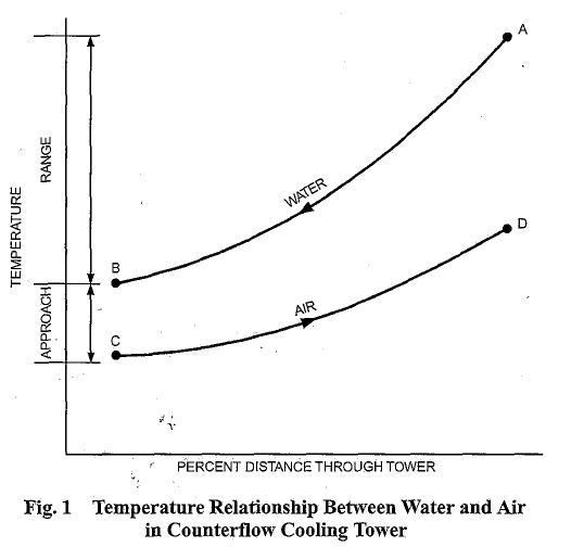
effect from sprays. A portion of the water absorbs heat to change from a liquid to a vapor at constant pressure. This heat of vaporization at atmospheric pressure is transferred from the water remaining in the liquid state into the airstream. Figure 1 shows the temperature relationship between water and air as they pass through a counter flow cooling tower. The curves indicate the drop in water temperature (A to B) and the rise in the air wet-bulb temperature (C to D) in their respective passages through the tower.
The temperature difference between the water entering and leaving the cooling tower (A minus B) is the range. For a Counter flow Cooling Tower steady-state system, the range is the same as the water temperature rise through the load heat exchanger, provided the flow rate through the cooling tower and heat exchanger are the same. Accordingly, the range is determined by the heat load and water flow rate, not by the size or thermal capability of the cooling tower.
The difference between the leaving water temperature and entering air wet-bulb temperature (B minus C) in Figure 1 is the approach to the wet bulb or simply the approach of the cooling tower. The approach is a method of cooling tower capability, and a larger cooling tower produces a closer approach (colder leaving water) for a given heat load, flow rate, and entering air condition. Thus, the amount of heat transferred to the atmosphere by the cooling tower is always equal to the heat load imposed on the tower, whereas the temperature level at which the heat is transferred is determined by the thermal capability of the cooling tower and the
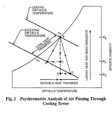
entering air wet-bulb temperature. Thermal performance of a cooling tower depends principally on the entering air wet-bulb temperature. The entering air dry-bulb temperature and relative humidity, taken independently, have an insignificant effect on thermal performance of mechanical-draft cooling towers, but do affect the rate of water evaporation in the cooling tower. A psychrometric analysis of the air passing through a cooling tower illustrates this effect (Figure 2). Air enters at the ambient condition Point A, absorbs heat and mass (moisture) from the water. and exits at Point B in a saturated condition (at verv light d ” loads, the discharge air may not be fully saturated). The amount of The preparation of this chapter is assigned to TC 8.6, Coollng Towers and heat transferred from the water to the air is proportional to the Evaporative Condensers. Reference in enthalpy of the air between the entering and leaving conditions (hB – hA). Because lines of constant enthalpy correspond
almost exactly to lines of constant wet-bulb temperature, the change in enthalpy of the air may be determined by the change in wet-bulb temperature of the air.
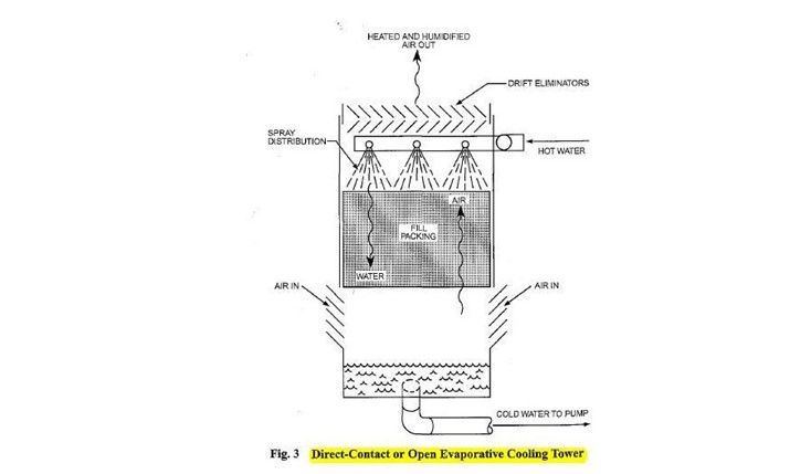
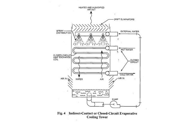
Two basic types of evaporative cooling devices are used. The first of these, the direct-contact or open cooling tower (Figure 3), exposes water directly to the cooling atmosphere, thereby transferring the source heat load directly to the air. The second type, often called a closed-circuit cooling tower, involves indirect contact between heated fluid and atmosphere (Figure 4), essentially combining a heat exchanger and cooling tower into one relatively compact device.
Of the direct-contact devices, the most rudimentary is a sprayfilled tower that exposes water to the air without any heat transfer medium or fill. In this device, the amount of water surface exposed to the air depends on the spray efficiency, and the time of contact depends on the elevation aid pressure ofthe water distribution system.
Ducts for Air Conditioning Systems
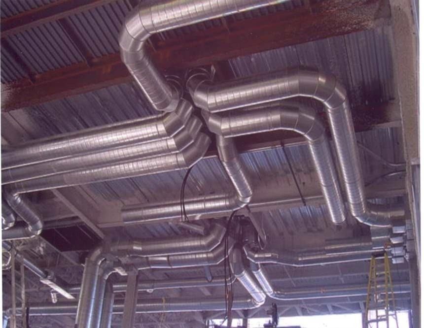
Fig 5 Duct design Photograph
Air flow problems have plagued the HVAC industry for years. No matter how much money you spend on a high-quality HVAC system, the equipment won’t work at its best without properly designed and installed ductwork. Ducts that are not well designed result in discomfort, high energy costs, bad air quality, and increased noise levels.
A well-designed ductwork system should deliver maximum interior comfort at the lowest operating cost while also preserving indoor air quality. The chief requirements of an air conditioning duct system are:
- It should convey specified rates of air flow to prescribed
- It should be economical in combined initial cost, fan operating cost and cost of building
- It should not transmit or generate objectionable
A primary issue is the tradeoff between the initial cost of the duct system and the energy cost of the air distribution system. Larger ducts require a larger initial investment, but result in lower fan energy costs over the life of the system. Other issues include space restrictions, noise level, capacity for expansion, appearance, etc.
This course will discuss the basic fundamentals and principles of air conditioning duct design and layout.
DUCTWORK DESIGN PRINCIPLES
Starting with the basics, let’s start at the most elementary level of air flow fundamentals.
Basic Definitions
The following basic terminology is extensively used in this course.
- cfm: volume of air flow; cubic feet/minute
- fpm: velocity or speed of air flow; feet/minute
- ft: duct size or cross-sectional area; square feet
Air volume in cfm can be calculated by multiplying the air velocity by the cross-sectional area of the duct in square feet.
- cfm = fpm x Area
Given any two of these three quantities, the third can be readily determined:
- fpm = cfm/area
- Area = cfm/fpm
Gauge and Absolute Pressures:
Gauge pressure is indicated on the gauge; absolute pressure is the total of the indicated gauge pressure plus atmospheric pressure. The general equation for absolute pressure is:
Gauge pressure + atmospheric pressure = absolute pressure
For example, if the gauge reads 10 psig then, using the above equation, the absolute pressure would be 24. 7 psia:
10 psig + 14.7 psi = 24.7psia
Ordinary heating, ventilating, and air conditioning duct systems read air pressures at 0.4 psi or less, often much less. 1 psi equals 27.7 inches of water gauge; a common duct pressure of 0.25 inches water column is equal to (0.25 divided by 27.7 in-wc/psi) = 0.009 psi.
Duct Pressure:
Duct system is pressurized by three pressures:
- Static pressure: It is the air pressure in the duct, which is used for fan
- Velocity pressure: It is the pressure generated by the velocity and weight of the air, which is used for measuring the flow (cfm) in a
- Total pressure: It is used to find velocity Static pressure plus velocity pressure equals total pressure.
Pressure in the ductwork is measured in inches of water column (in-wc).
Standard Air Density:
Air has mass. Standard air has a density of 0.075 lbs/ ft3.
System capacity is directly affected by changes in air flow. As air is heated or humidified, its specific volume increases and its density decreases. If the air density is low, more
cfm is required to keep the mass flow rate the same. If air density is not considered, many systems will have very low air flow.
Correction for the density is however not needed in air conditioning or cooling applications, if the temperature is between 40°F to 100°F and up to 1000 ft. in elevation.
Fan Capacity:
The volume of air will not be affected in a given system because a fan will move the same amount of air regardless of the air density. In other words, if a fan will move 3,000 cfm at 70°F, it will also move 3,000 cfm at 250°F
Volumetric Air Flow Rate:
The volumetric flow rate of air that will be conveyed through the duct in an air conditioning system is determined by the cooling/heat load and the desired supply air temperature. Since we are not conditioning cfms of air but rather pounds of it, we need a mass-balance equation:
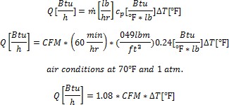
It is important that the air conditioning ductwork system delivers and return the right amount of air from each room and provide comfort year round. This implies room by room heat loss and heat gain calculations.
Air Flow Principles
Flow of air is caused as a result of pressure differential between two points. Flow will originate from an area of high energy (or pressure) and proceed to area(s) of lower energy.
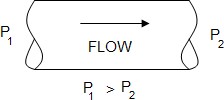
Fig 6 Air flow movement
Air moves according to three fundamental laws of physics: conservation of mass, conservation of energy, and conservation of momentum.
- Conservation of mass: It simply states that an air mass is neither created nor From this principle it follows that the amount of air mass coming into a junction in a ductwork system is equal to the amount of air mass leaving the junction, or the sum of air masses at each junction is equal to zero. In most cases the air in a duct is assumed to be incompressible, an assumption that overlooks the change of air density that occurs as a result of pressure loss and flow in the ductwork. In ductwork, the law of conservation of mass means a duct size can be recalculated for a new air velocity using the simple equation:
V2 = (V1 * A1)/A2
where V is velocity and A is Area
- The law of energy conservation: It states that energy cannot disappear; it is only converted from one form to This is the basis of one of the main expression of aerodynamics, the Bernoulli equation. Bernoulli’s equation in its simple form shows that, for an elemental flow stream, the difference in total pressures between any two points in a duct is equal to the pressure loss between these points, or:
(Pressure loss) 1-2 = (Total pressure) 1 – (Total pressure) 2
- Conservation of momentum: It is based on Newton’s law that a body will maintain its state of rest or uniform motion unless compelled by another force to change that state. This law is useful to explain flow behavior in a duct system’s fitting.
Total Pressure, Velocity Pressure, and Static Pressure
Air flow through a duct system creates three types of pressures: static, dynamic (velocity), and total.
- Static pressure: Static Pressure is the pressure that causes air in the duct to Static pressure is the outward push of air against duct surfaces and is a measure of resistance when air moves through an object like duct work. Measured in inches of water column (in-wc), it acts equally in all directions and is independent of velocity.
- Velocity pressure: Velocity pressure is the pressure caused by air in It is equal to the product of air density and the square of the velocity divided by 2.
VP = 0.5 x ρ x v2
Using standard air, the relationship between V and VP is given by:
![]()
VP will only be exerted in the direction of air flow and is always positive.
- Total Pressure: Total pressure is the algebraic sum of velocity pressure and static
TP = VP + SP
- TP = Total Pressure
- VP = VelocityPressure
- SP = Static Pressure
Air Flow Characteristics in Duct
- At any point, the total pressure is equal to the sum of the static and velocity
- The static pressure is exerted equally in all directions and the velocity pressure is exerted only in the direction of air This makes it difficult to directly measure velocity pressure in a duct. Simply put, because static pressure is also pushing in the direction of air flow, you can never measure just velocity pressure. Practically, velocity pressure is calculated by measuring pressure perpendicular to the air flow (Static Pressure) and also measuring pressure parallel to the air flow (Total Pressure).
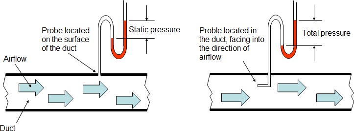
Fig 7 Total pressure variation
Once you have these two values you can just subtract static pressure from the total pressure and derive the velocity pressure. VP = TP – SP
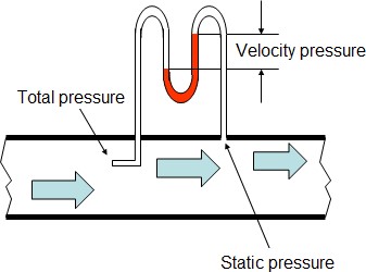
Fig 8 Static pressure variation
- Static and velocity pressure are mutually The magnitude of each is dependent on the local duct cross-section which determines the flow velocity. The following pressure changes are affected in the ducts:
- Constant cross-sectional areas: Total and static losses are
- Diverging sections (increase in duct size): Velocity pressure decreases, total pressure decreases, and static pressure may increase (static regain).
- Converging sections (decrease in duct size): Velocity pressure increases in the direction of flow, total and static pressure
- The total pressure generally drops along the air flow because of frictional and turbulence
Confusion in the use of the terms “Static Pressure”, “Velocity Pressure” and “Total Pressure” is widely prevalent among HVAC engineers and contractors. The term “Static Pressure” is typically used for fan selection; “Velocity Pressure” is used for
measuring cfm in a system, and “Total Pressure” is used to find the velocity pressure. Total Pressure determines the actual mechanical energy that must be supplied to the system.
DUCT COMPONENTS & MATERIALS
The air distribution system will have a designation depending on the function of the duct. Broadly, there are five designations of ducts:
- Supply air ductwork supplies conditioned air from the air handling unit to the conditioned
- Return air ductwork removes air from the conditioned building spaces and returns the air to the air handling unit, which reconditions the In some cases, part of the return air in this ductwork is exhausted to the building exterior.
- Fresh air ductwork supplies outdoor air to the air handling Outdoor air is used for ventilating the occupied building space.
- Exhaust (relief) air ductwork carries and discharges air to the Exhaust air is taken from toilets, kitchen, laboratories and other areas requiring ventilation.
- Mixed air ductwork mixes air from the outdoor air and the return air then supplies this mixed air to the air handling
Duct Components
The figure below shows a schematic and a 3-D representation of supply and return air ductwork. The central air handling unit (AHU) is connected to the air plenum at the starting point. AHU fans draw in air through grilles called returns and force air through the plenum and into the conditioned space through supply registers.
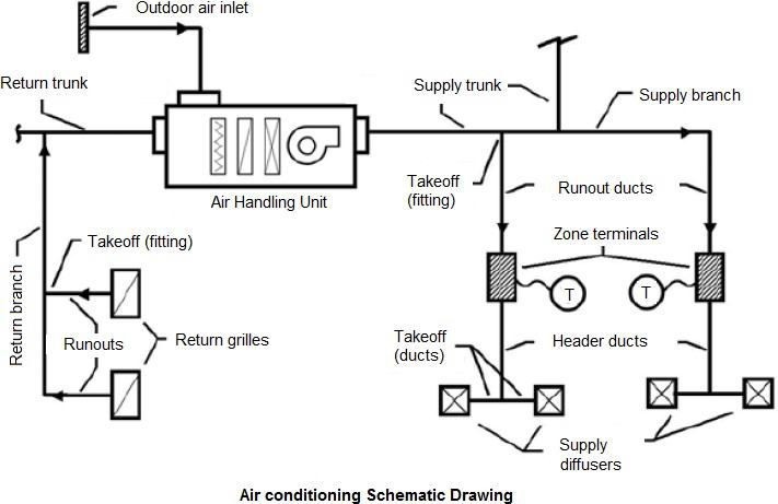
Fig 9 Air Conditioing Schematic Diagram
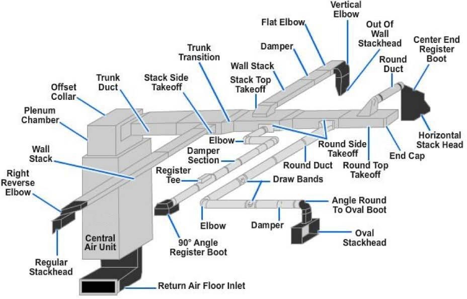
Fig 10. Components of Ducts
The duct components are as follows:
Plenum or Main Trunk: The plenum is the main part of the supply and return duct system that goes directly from the air handler to the “Trunk Duct”.
Trunk Duct: A duct that is split into more than one duct is called a “trunk”, just like a tree. Ducts that are on the end of a trunk and terminate in a register are called branches.
Take Off: Branch ducts are fastened to the main trunk by a takeoff-fitting. The takeoff encourages the air moving the duct to enter the takeoff to the branch duct.
Air Terminals Devices: Air terminals are the supply air outlets and return or exhaust air inlets. For supply, diffusers are most common, but grilles and registers are also used widely. A diffuser is an outlet device discharging supply air in a direction radially to the axis of entry. A register is a grille equipped with a volume control damper. A grille is without a damper.
Duct Materials
Ducting is generally formed by folding sheet metal into the desired shape. Traditionally, air conditioning ductwork is made of galvanized steel, next in popularity is aluminum. Other metals used under special circumstances are copper and stainless steel. Metals that are used extensively depend on the application of the duct and are listed below:
- Galvanized Steel: It is a standard, most common material used in fabricating ductwork for most comfort air conditioning The specifications for galvanized steel sheet are ASTM A653, coating G90.
- Aluminium: It is widely used in clean room These are also preferred systems for moisture laden air, special exhaust systems and ornamental duct systems. The specifications for Aluminium sheet are ASTM B209, alloy 1100, 3003 or 5052.
- Stainless Steel: It is used in duct systems for kitchen exhaust, moisture laden air, and fume The specifications for stainless steel sheet are ASTM A167, Class 302 or 304, Condition A (annealed) Finish No. 4 for exposed ducts and Finish No. 2B for concealed duct.
- Carbon Steel (Black Iron): It is widely used in applications involving flues, stacks, hoods, other high temperature and special coating requirements for industrial
- Copper: It is mainly used for certain chemical exhaust and ornamental
Pressure in the air conditioning ducts is small, so materials with a great deal of strength are not needed. The thickness of the material depends on the dimensions of the duct, the length of the individual sections, and the cross-sectional area of the duct.
Non-Metallic ducts
This category includes ducts made from plastic or foam boards, shaped by cutting and folded to produce the required cross-sectional geometry. Boards are faced usually with an aluminum coating, both internal and external.
The main drawback of this type of ducting is its fire classification. Even if it complies with local standards, when exposed to fire, it often exhibits poor performance in terms of the production of both smoke and flaming droplets.
- Fibreglass Reinforced Plastic (FRP): It is used mainly for chemical exhaust, scrubbers, and underground duct Advantages are resistance to corrosion, self-insulation, excellent sound attenuation and high quality sealing. Limiting characteristics include cost, weight, range of chemical and physical properties, and code acceptance.
- Polyvinyl Chloride (PVC): It is used for exhaust systems for chemical fumes and underground duct Advantages include resistance to corrosion, light weight, and ease of modification. Limiting characteristics include cost, fabrication, code acceptance, thermal shock, and weight.
- Fabric: Fabric ducting, also known as textile ducts, is usually made of special permeable polyester material and is normally used where even air distribution is Due to the nature or the air distribution, textile ducts are not usually concealed within false ceilings. Condensation is not a concern with fabric ducts and therefore these can be used where air is to be supplied below the dew point without insulation.
- Flex Duct: Flex ducts consist of a duct inner liner supported on the inside by a helix wire coil and covered by blanket insulation with a flexible vapor barrier jacket on the outside. Flex ducts are often used for runouts, as well as with metal collars used to connect the flexible ducts to supply plenums, trunks and branches constructed from sheet metal or duct board. Flex ducts provide convenience of installation as these can be easily adapted to avoid clashes but has certain disadvantages. These have more friction loss inside them than metal ducting. Flex duct runs should be as short as possible (5 to 6 ft. max.) and should be stretched as tight as possible.
DUCT CLASSIFICATION
Ducts are classified in terms of velocity and pressure.
Velocity Classification
Ducts are classified into 3 basic categories:
- Low Velocity Systems: They are characterized by air velocities up to 2000
- Medium Velocity Systems: They are characterized by air velocities in the range of 2,000 to 2,500
- High Velocity Systems: They are characterized by air velocities greater than 2,500
The low velocity system is used in most air conditioning installations because it is quieter, has lower friction losses, lower fan power, and lower air leakage.
High duct velocities result in lower initial costs but require increased fan static pressures; therefore, resulting in increased operating costs. Often these need additional noise attenuation (use of noise silencers) and are not suitable for comfort applications.
Generally, high-velocity systems are applicable to large multi-story buildings, primarily because the advantage of savings in duct shafts and floor-to-floor heights is more substantial. Small two- and three-story buildings are normally low velocity. A velocity of 1,000 to 1,500 fpm for main ducts and a velocity of 700 to 1,000 fpm for the branch take offs are recommended.
Pressure Classification
Duct systems are also divided into three pressure classifications, matching the way supply fans are classified.
- Low Pressure: The term low-pressure applies to systems with fan static pressures less than 3 inches Generally, duct velocities are less than 1,500 fpm.
- Medium Pressure: The term medium pressure applies to systems with fan static pressures between 3 to 6 inches Generally, duct velocities are less than or equal to 2,500 fpm.
- High Pressure: The term high pressure applies to systems with fan static pressures between 6 to 10 inches Usually the static pressure is limited to a maximum of 7 inches WC, and duct velocities are limited to 4,000 fpm. Systems requiring pressures more than 7 inches WC are normally unwarranted and could result in very high operating costs.
General good engineering practices are:
- Use of medium pressure classification for primary air ductwork (fan connections, risers, and main distribution ducts).
- Use of low pressure classification for secondary air ductwork (run- outs/branches from main to terminal boxes and distribution devices).
Velocity Classification vs. Pressure Classification
- Duct pressure classification influences the duct strength, deflection and air
- Duct velocity classification influences noise, vibration, friction losses and fan
4.0. DUCT SHAPES
Ducts commonly used for carrying air are of round, square, or rectangular shape. All have advantages and disadvantages, and find applications where one is definitely superior to the other

.
Fig 11. Duct Shapes
Round Ducts
The duct shape that is the most efficient (offers the least resistance) in conveying moving air is a round duct, because it has the greatest cross-sectional area and a minimum contact surface. In other words, it uses less material compared to square or rectangular ducts for the same volume of air handled.
An 18 inch diameter duct, for example, has the same air-carrying capacity as a 26” x 11” rectangular duct. The round duct has a cross-sectional area of 254.5 sq.-in and a perimeter of 4.7 ft., while the rectangular duct has a 286 sq.-in area and a perimeter of
- The rectangular duct thus has 32% more metal in it and would cost proportionately more. Also the insulation, supports and labor are higher for rectangular ducts of similar capacity. Some of the advantages of round ductwork include:
- Round shape results in lower pressure drops, thereby requiring less fan horsepower to move the air and, consequently, smaller
- Round shape also has less surface area and requires less insulation when externally wrapped.
- Round ducts are available in longer lengths than rectangular ducts, thereby eliminating costly field Spiral lock-seams add rigidity; therefore, spiral ducts can be fabricated using lighter gauges than longitudinal seam ducts. Spiral ducts leak less and can be more easily sealed compared to rectangular ducts.
- The acoustic performance of round and oval ducts is superior because their curved surfaces allow less breakout The low-frequency sound is well contained in round ducts.
- Round ducts can help promote healthier indoor Less surface area, no corners and better air flow reduce the chance of dirt and grime accumulating inside the duct and, therefore, becoming a breeding ground for bacterial growth.
While round air ducts have great advantages, there are some disadvantages to them. One of the most notable drawbacks of round air ducts is that they need more clear height for installation. If the net clear height of a furred space above a suspended ceiling is 14 inches, an 18-in diameter duct cannot be installed therein; however, its equivalent 26” x 11” rectangular duct will fit the space easily. A combination of a rectangular plenum and round branches sometimes is a good compromise.
Rectangular Ducts
Square or rectangular ducts fit better to building construction. They fit above ceilings and into walls, and they are much easier to install between joists and studs.
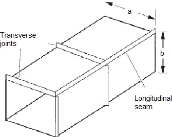
Fig 12. Rectangular Ducts
When rectangular ducts must be used due to space limitations, keep the width-to- height ratio (aspect ratio) low. A rectangular duct section with an aspect ratio close to 1 yields the most efficient rectangular duct shape in terms of conveying air. A duct with an aspect ratio above 4 is much less efficient in use of material and experiences great pressure losses. Aspect ratios of 2 to 3 are ideal in trading off added duct cost of material and fan energy for headroom savings.
Disadvantages of rectangular ducts are as follows:
- They create higher pressure drop;
- They use more pounds of metal for the same air-flow rate as round ducts;
- Their joint length is limited to the sheet widths stocked by the contractor;
- Their joints are more difficult to seal;
- Those with high aspect ratio can transmit excessive noise if not properly
Oval Ducts
Flat oval ducts have smaller height requirements than round ducts and retain most of the advantages of the round ducts. However, fittings for flat oval ducts are difficult to fabricate or modify in the field. Other disadvantages include:
- Difficulty of handling and shipping larger sizes;
- Tendency of these ducts to become more round under pressure; and,
- In large aspect ratios, difficulties of assembling oval slip
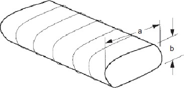
Fig 13. Oval Ducts
Equivalent Diameter
Since both round and rectangular ducts are extensively used in air conditioning systems, it is quite possible that a contractor may wish to substitute one for the other while working on new construction or modifying an existing system. With this likelihood, there is the general tendency to substitute cross-sectional areas of round and rectangular ducts. This is improper and will affect air distribution system performance. Therefore, it is necessary for the HVAC designer to fully understand the conditions under which round and rectangular ducts can be interchanged. The important thing is the duct pressure drop and that’s where the concept of “equivalent diameter” comes into picture.
By definition, equivalent diameter (Deq) is the diameter of a circular duct that will give the same pressure drop at the same air flow as the rectangular duct.
From ASHRAE Fundamentals Handbook, the following equations may be used to convert rectangular and flat oval ducts to and from round.


![]()
![]()
where,
- p = perimeter of oval duct (in.)
- A = cross-sectional area (sq.-in)
- a = length of major axis (in.)
- b = length of minor axis (in.)
Equivalent Diameter vs. Equivalent Cross-sectional Area Approach
Consider an air flow rate of 7,500 cfm and compare a 30” diameter round duct to equivalent rectangular and oval duct options.
Equivalent Diameter Approach
For a given round duct diameter (30 inches), the dimensions for rectangular and flat oval ducts must be solved for by trial and error. Fix one dimension and substitute in the equations above. Let’s use 16 inches for the minor axis, then the equivalent rectangular duct dimension will be 16”X 51”, and flat oval ducts with a 16-in. minor axis will be 16” X 53”.
What this means is that all three ducts, 30” round, 16” x 51” rectangular, and 16” x 53” flat oval will have the same friction loss for a given cfm. The table below summarizes the equivalent diameter approach.
See also:
Psychrometry and Air Conditioning II
Vapour Absorption Refrigeration
